 10955
10955
DG'hAck 2020 - Strange Thing (reverse)

DG’hAck 2020 - Stranger Thing (reverse)
This challenge was about reversing an AVR binary running on an Arduino UNO (ATmega328P). At my validation time we were only 2 to have solved it.
Edit: You should definitively check this write-up of a friend.
Format recognization
The following file was given :
head strange_thing.hex
:100000000C945C000C946E000C946E000C946E00CA
:100010000C946E000C946E000C946E000C946E00A8
:100020000C946E000C946E000C946E000C946E0098
:100030000C946E000C946E000C946E000C946E0088
:100040000C940F010C946E000C946E000C946E00D6
:100050000C946E000C946E000C946E000C946E0068
:100060000C946E000C946E00000000002400270029
:100070002A0000000000250028002B0004040404CE
:100080000404040402020202020203030303030342
:10009000010204081020408001020408102001021F
There are 2 ways to identify this kind of file :
- You already know the format.
- You copy / paste one line on Google.
I had the chance to already have seen a file like this but I didn’t remember where so I copy pasted 100000000C945C000C946E000C946E000C946E00CA on Google and all links made reference to Arduino programs.
This is in fact a program running in the flash of an Arduino in the Intel Hex format. It’s a bare metal program which runs directly on the microcontroller without OS unlike our laptop.
Decoding the data
For this I installed through pip intelhex which comes with some scripts.
pip install intelhexThen you can decode it :
$ hex2bin.py strange_thing.hex
$ file chall.bin
chall.bin: data

$ strings chall.bin
     h>s@
Nothing fancy.
Background
I only did AVR once, it was during my training session with ANSSI at Irt Systemx for the French CTF team. I got a presentation of the microcontroller and it’s ISA.
Before trying to reverse this challenge I went through the doc I received for the training. I was looking for how the program will try to communicate with me, may this be through input or output. I was wondering how I could send something like a password and get back the flag.
So we gonna get some AVR and arduino UNO information before to start
AVR and Arduino UNO
I had this tiny program from my training and the associated binary and hex file. So I started its analyze.
#include <util/delay.h>
#include <avr/io.h>
#include <stdint.h>

#define LED (1 << 5) // PIN 13 is the embedded led
#define PRG_MASK 0x1A
#define PRG_THRESHOLD 201

uint8_t PRG(uint8_t* x_n, uint8_t* x_n_1)
{
    uint8_t tmp = (*x_n + *x_n_1);

    if(tmp > PRG_THRESHOLD) // pseudo modulo
    {
        tmp = tmp - PRG_THRESHOLD;
    }

    // propagate old values
    *x_n_1 = *x_n;
    *x_n = tmp;

    // return 1 only if the mask is found
    return (tmp & PRG_MASK) == PRG_MASK;
}

int main()
{
    //init
    DDRB = LED;
    uint8_t x_n = 1;
    uint8_t x_n_1 = 4;
    uint8_t random_value;

    // main loop
    while(1)
    {
        // takes a bit, light on PIN13's led if 1
        random_value = PRG(&x_n, &x_n_1);
        if(random_value)
        {
            PORTB = LED;
        }
        else
        {
            PORTB = 0x00;
        }
        _delay_ms(20);
    }
}
You can get the disassembly of the binary with avr-objdump.
$ avr-objdump -l -t -D -S output/main.bin > main.disDisassembly of section .text:
00000000 <__vectors>:
__vectors():
   0:   0c 94 34 00     jmp     0x68    ; 0x68 <__ctors_end>
4: 0c 94 3e 00 jmp 0x7c ; 0x7c <__bad_interrupt>
8: 0c 94 3e 00 jmp 0x7c ; 0x7c <__bad_interrupt>
c: 0c 94 3e 00 jmp 0x7c ; 0x7c <__bad_interrupt>
10: 0c 94 3e 00 jmp 0x7c ; 0x7c <__bad_interrupt>
14: 0c 94 3e 00 jmp 0x7c ; 0x7c <__bad_interrupt>
18: 0c 94 3e 00 jmp 0x7c ; 0x7c <__bad_interrupt>
1c: 0c 94 3e 00 jmp 0x7c ; 0x7c <__bad_interrupt>
20: 0c 94 3e 00 jmp 0x7c ; 0x7c <__bad_interrupt>
24: 0c 94 3e 00 jmp 0x7c ; 0x7c <__bad_interrupt>
28: 0c 94 3e 00 jmp 0x7c ; 0x7c <__bad_interrupt>
2c: 0c 94 3e 00 jmp 0x7c ; 0x7c <__bad_interrupt>
30: 0c 94 3e 00 jmp 0x7c ; 0x7c <__bad_interrupt>
34: 0c 94 3e 00 jmp 0x7c ; 0x7c <__bad_interrupt>
38: 0c 94 3e 00 jmp 0x7c ; 0x7c <__bad_interrupt>
3c: 0c 94 3e 00 jmp 0x7c ; 0x7c <__bad_interrupt>
40: 0c 94 3e 00 jmp 0x7c ; 0x7c <__bad_interrupt>
44: 0c 94 3e 00 jmp 0x7c ; 0x7c <__bad_interrupt>
48: 0c 94 3e 00 jmp 0x7c ; 0x7c <__bad_interrupt>
4c: 0c 94 3e 00 jmp 0x7c ; 0x7c <__bad_interrupt>
50: 0c 94 3e 00 jmp 0x7c ; 0x7c <__bad_interrupt>
54: 0c 94 3e 00 jmp 0x7c ; 0x7c <__bad_interrupt>
58: 0c 94 3e 00 jmp 0x7c ; 0x7c <__bad_interrupt>
5c: 0c 94 3e 00 jmp 0x7c ; 0x7c <__bad_interrupt>
60: 0c 94 3e 00 jmp 0x7c ; 0x7c <__bad_interrupt>
64: 0c 94 3e 00 jmp 0x7c ; 0x7c <__bad_interrupt>
00000068 <__ctors_end>:
__trampolines_start():
  68:   11 24           eor     r1, r1
  6a:   1f be           out     0x3f, r1        ; 63
  6c:   cf ef           ldi     r28, 0xFF       ; 255
  6e:   d8 e0           ldi     r29, 0x08       ; 8
  70:   de bf           out     0x3e, r29       ; 62
  72:   cd bf           out     0x3d, r28       ; 61
  74:   0e 94 51 00     call    0xa2    ; 0xa2 <main>
  78:   0c 94 73 00     jmp     0xe6    ; 0xe6 <_exit>
0000007c <__bad_interrupt>:
__vector_22():
7c: 0c 94 00 00 jmp 0 ; 0x0 <__vectors>
00000080 <PRG>:
PRG():
80: fc 01 movw r30, r24
82: 80 81 ld r24, Z
84: db 01 movw r26, r22
86: 9c 91 ld r25, X
88: 98 0f add r25, r24
8a: 9a 3c cpi r25, 0xCA ; 202
8c: 08 f0 brcs .+2 ; 0x90 <PRG+0x10>
8e: 99 5c subi r25, 0xC9 ; 201
90: db 01 movw r26, r22
92: 8c 93 st X, r24
94: 90 83 st Z, r25
96: 9a 71 andi r25, 0x1A ; 26
98: 81 e0 ldi r24, 0x01 ; 1
9a: 9a 31 cpi r25, 0x1A ; 26
9c: 09 f0 breq .+2 ; 0xa0 <PRG+0x20>
9e: 80 e0 ldi r24, 0x00 ; 0
a0: 08 95 ret
000000a2 <main>:
main():
a2: cf 93 push r28
a4: df 93 push r29
a6: 00 d0 rcall .+0 ; 0xa8 <main+0x6>
a8: cd b7 in r28, 0x3d ; 61
aa: de b7 in r29, 0x3e ; 62
ac: 80 e2 ldi r24, 0x20 ; 32
ae: 84 b9 out 0x04, r24 ; 4
b0: 81 e0 ldi r24, 0x01 ; 1
b2: 89 83 std Y+1, r24 ; 0x01
b4: 84 e0 ldi r24, 0x04 ; 4
b6: 8a 83 std Y+2, r24 ; 0x02
b8: 10 e2 ldi r17, 0x20 ; 32
ba: be 01 movw r22, r28
bc: 6e 5f subi r22, 0xFE ; 254
be: 7f 4f sbci r23, 0xFF ; 255
c0: ce 01 movw r24, r28
c2: 01 96 adiw r24, 0x01 ; 1
c4: 0e 94 40 00 call 0x80 ; 0x80 <PRG>
c8: 88 23 and r24, r24
ca: 11 f0 breq .+4 ; 0xd0 <main+0x2e>
cc: 15 b9 out 0x05, r17 ; 5
ce: 01 c0 rjmp .+2 ; 0xd2 <main+0x30>
d0: 15 b8 out 0x05, r1 ; 5
d2: 2f ef ldi r18, 0xFF ; 255
d4: 89 ef ldi r24, 0xF9 ; 249
d6: 90 e0 ldi r25, 0x00 ; 0
d8: 21 50 subi r18, 0x01 ; 1
da: 80 40 sbci r24, 0x00 ; 0
dc: 90 40 sbci r25, 0x00 ; 0
de: e1 f7 brne .-8 ; 0xd8 <main+0x36>
e0: 00 c0 rjmp .+0 ; 0xe2 <main+0x40>
e2: 00 00 nop
e4: ea cf rjmp .-44 ; 0xba <main+0x18>I only kept the .text disassembly as we don’t care about the rest for the moment.
Memory organization
The first thing to know is which is the address of start of the flash (which is holding this binary). From the ATmega328P datasheet (the microcontroller of the Arduino UNO) we know that is just 0x0.
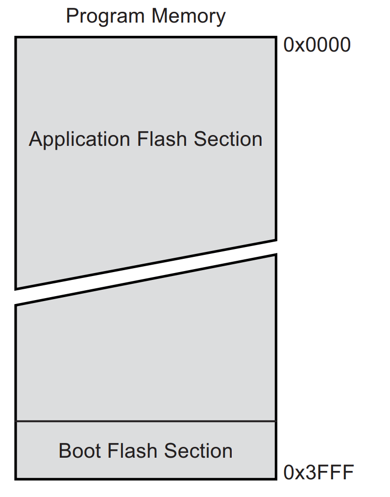
So the very first instruction executed is at 0x0 in our binary and so is in the vector table.
00000000 <__vectors>:
__vectors():
0: 0c 94 34 00 jmp 0x68 ; 0x68 <__ctors_end>It will directly jump into __ctors_end or __trampolines_start section which will make some stack initialization and then call main.
00000068 <__ctors_end>:
__trampolines_start():
68: 11 24 eor r1, r1
6a: 1f be out 0x3f, r1 ; 63
6c: cf ef ldi r28, 0xFF ; 255
6e: d8 e0 ldi r29, 0x08 ; 8
70: de bf out 0x3e, r29 ; 62
72: cd bf out 0x3d, r28 ; 61
74: 0e 94 51 00 call 0xa2 ; 0xa2 <main>
78: 0c 94 73 00 jmp 0xe6 ; 0xe6 <_exit>You said stack initialization, but what about stack layout ?
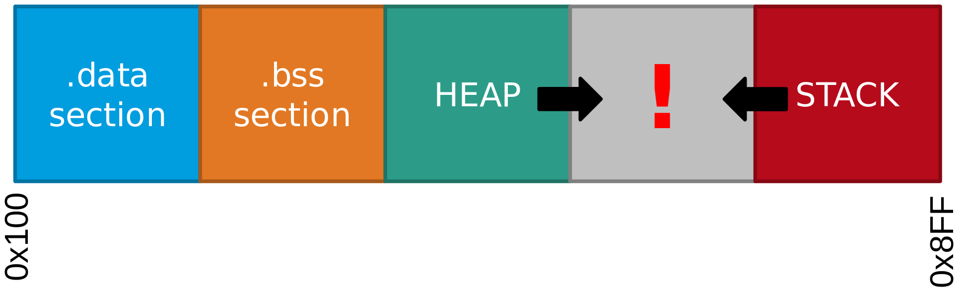
The base address of the stack will always be 0x8ff and will grow down to 0x100 a bit like a classic stack in GNU program.
However the stack pointer are hold in 2 registers called SPL (0x3D) and SPH (0x3E) so as you see above the instructions starting at 0x6c is setting 0x8FF split in 2 registers r28 and r29. Then the out instruction is writing the value in the SPL and SPH registers.
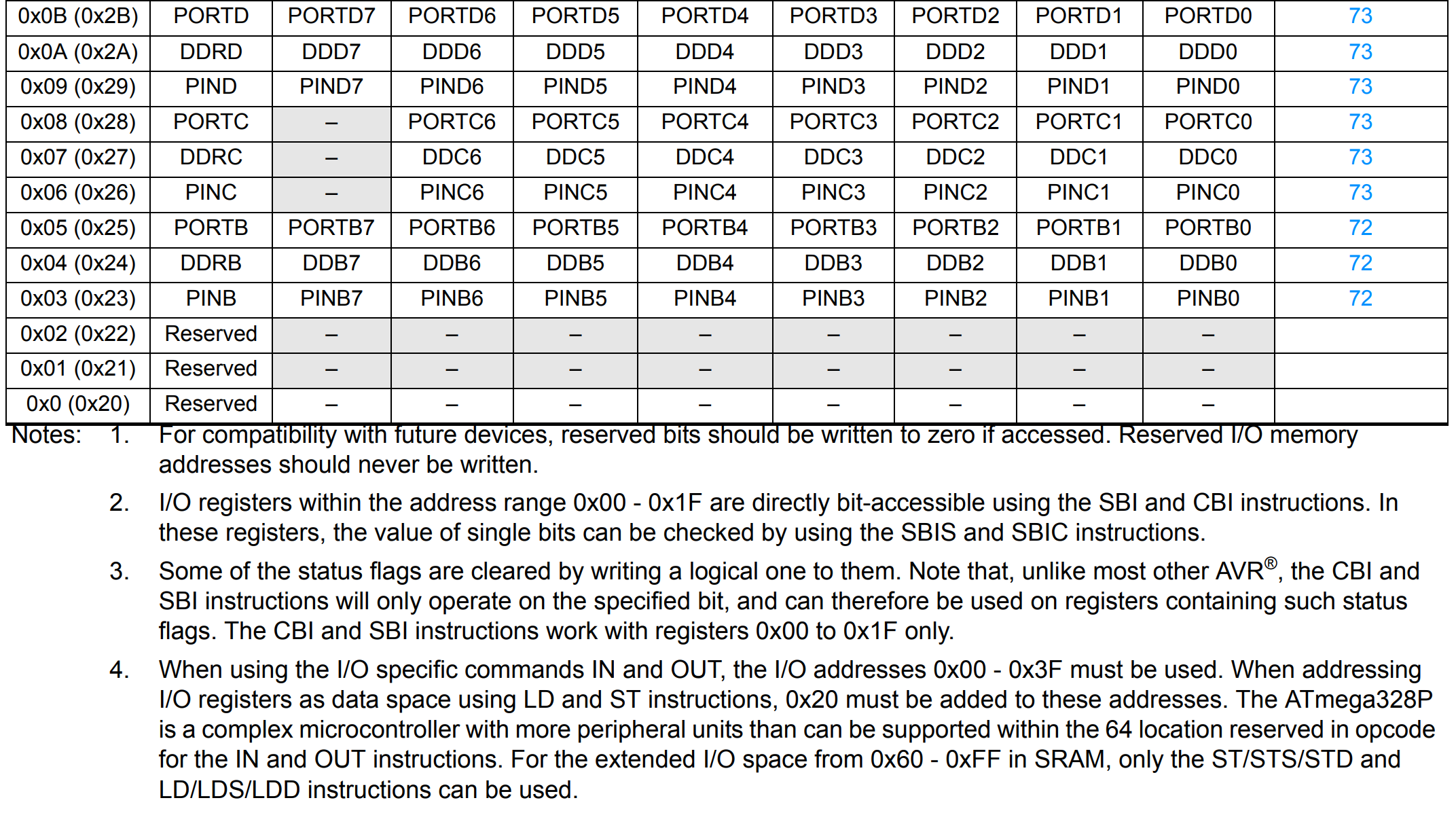
Here is the full memory layout of the CPU :
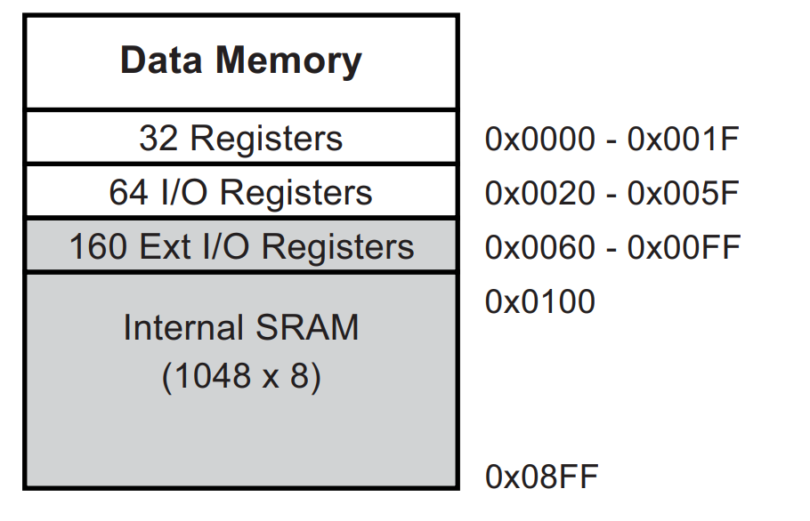
Something I have learn few weeks ago is memory mapped I/O. It allows the CPU to communicate with peripheral devices. It’s something new if you come from Linux as it’s the kernel we do the abstraction. Here, in embedded devices world there is often no kernel to do this abstraction.
If you want to talk with your peripherals devices you need to access them through I/O mapped into the CPU memory.
The page 0x0 - 0x01F is reserved for the 32 registers and 0x20 - 0x5F of 64 I/O (see 30. Register Summary in the datasheet). There are some extended I/O until 0xFF. Right after the RAM as seen before.
You could imagine that general registers are mapped at the same address as the flash but it’s not. The instruction will do the work to choose if they will access the flash or registers (Harvard architecture)
Make the led blink again
The purpose of this program is to make the led blink (modulo a condition). Let’s try to understand how it’s achieved.
In order to do this there are 3 important instructions.
#define LED (1 << 5) // PIN 13 is the embedded led
[...]
DDRB = LED;
[...]
PORTB = LED;
But first we also need to understand the I/O.
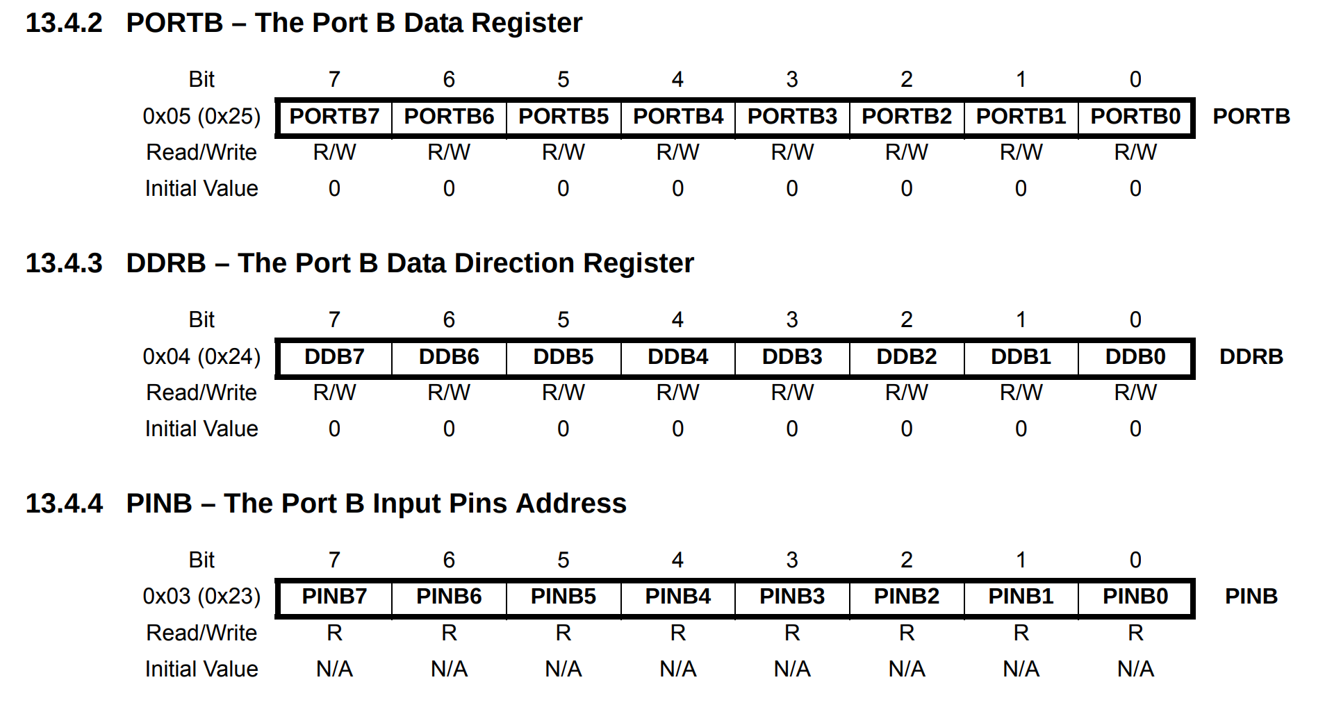
They are split between 3 ports / pins :B, C, D we refer to PINX or PORTX depending if we want read or write. If reading we use PINX, for writing PORTX.
But before reading or writing from it we have to set the mode by setting or unsetting the DDBX bit in DDRX setting the pin in write mode. If set it’s output if not, input.
In the define we set the constant LED to 1 << 5 which is 32 I wondered why this specific value but it makes totally sense with the right schema :
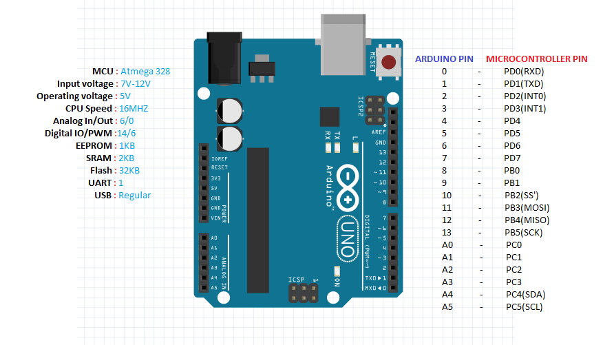
The PIN 13 is named PB5
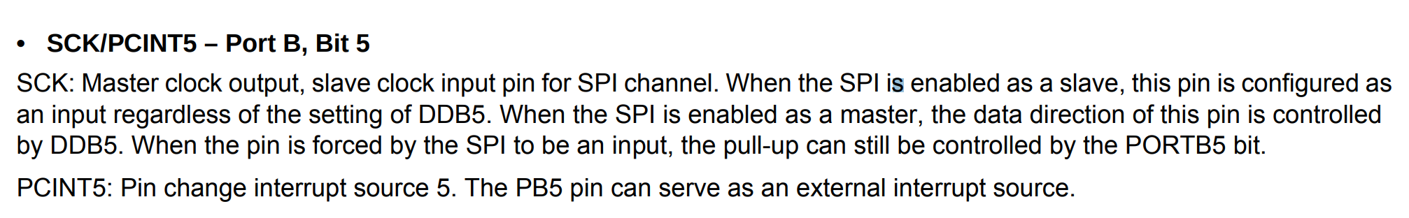
So the associated port is the B and the associated bit is the 5 so if we want to set the DDB5 bit up in the DDRB register we have to set the 6th bit to one 100000 == (32)
To recapitulate we have to found the right DDRX and then set the DDBX associated to the pin in input or output mode
DRB = LED; // 100000bNow we can send a value in the PORT, this will write 1 to the PIN 13
PORT = LED; // 100000bNow let’s seem from an assembly point of view :
; set 32 in DDRB (DDB5 = 1)
; set write mode
ac:   80 e2           ldi     r24, 0x20       ; 32
ae:   84 b9           out     0x04, r24       ; 4
[...]
; set 32 in PORTB (PORTB5 = 1)
; sent a 1
cc:   15 b9           out     0x05, r17       ; 5
The OUT instruction store a value from the 2nd operand register (Register File Space) to the I/O space.
So now why the value 0x04 and 0x05.
As you can read 0x04 == DDRB and 0x05 == PORTB.
If you remember I said before that the I/O namespace start at 0x20. However with the IN and OUT instructions we must decrement it by 0x20 (point 4 in the screenshot).
We now understand how I/O works with Aduino. We can starts reversing the binary.
Reversing the challenge
We can now detect how interact the binary with us by looking for IN, OUT instruction. We first need to get the disassembly
$ avr-objdump -b binary -m avr -D decoded.bin > chall.dis$ egrep "int|out" chall.dis
ba: 1f be out 0x3f, r1 ; 63
c0: de bf out 0x3e, r29 ; 62
c2: cd bf out 0x3d, r28 ; 61
126: 2f bf out 0x3f, r18 ; 63
14e: 24 bd out 0x24, r18 ; 36
194: 3f bf out 0x3f, r19 ; 63
29e: 0f be out 0x3f, r0 ; 63
2b8: 84 bd out 0x24, r24 ; 36
2be: 84 bd out 0x24, r24 ; 36
2c4: 85 bd out 0x25, r24 ; 37
2ca: 85 bd out 0x25, r24 ; 37
36c: 8f bf out 0x3f, r24 ; 63There is no mapped I/O interesting for us, when I say interesting I talk about the 13 pins available. These out value are not for communicate with us but for program initialization. Moreover there is no IN to get input.
For me it was strange, then I wondered how does the Arduino standard library was communicating with the pins. I took the most simple program ever :
void setup() {
  // initialize digital pin LED_BUILTIN as an output.
  pinMode(LED_BUILTIN, OUTPUT);
}

// the loop function runs over and over again forever
void loop() {
  digitalWrite(LED_BUILTIN, HIGH);   // turn the LED on (HIGH is the voltage level)
  delay(1000);                       // wait for a second
  digitalWrite(LED_BUILTIN, LOW);    // turn the LED off by making the voltage LOW
  delay(1000);                       // wait for a second
}
They do it with the digitalWrite function, I then compiled this program and did grep things again (as the binary is of course statically linked the code of digitalWrite is in the binary). But still nothing, they must use something else to communicate …
I looked for the source and to be honest I didn’t really understood the last steps …
- https://garretlab.web.fc2.com/en/arduino/inside/hardware/arduino/avr/cores/arduino/wiring_digital.c/digitalWrite.html
- https://garretlab.web.fc2.com/en/arduino/inside/hardware/arduino/avr/cores/arduino/Arduino.h/portOutputRegister.html
Emulation
At this moment I didn’t wanted to reverse the whole binary has it contains code from common library and I’m not enough confident with avr to go through. I could use IDA Diaphora for diffing code but I wasn’t sure about the result.
- https://blog.attify.com/flare-4-ctf-write-part-4/
However I find a gold project named simavr which let you emulate the program. Let’s install it.
$ yay avr-gcc
$ yay avr-core
$ sudo pacman -S freeglut
$ git clone https://github.com/buserror/simavr.git
$ cd simavr
$ make
Now you should have the simduino binary under ./examples/board_simduino/obj-x86_64-pc-linux-gnu/simduino.elf
We can run the hex file directly :
$ ./examples/board_simduino/obj-x86_64-pc-linux-gnu/simduino.elf  ~/nextcloud/CTF/dghack/reverse/strange/strange_thing.hex

atmega328p booloader 0x00000: 18218 bytes
avr_special_init
uart_pty_init bridge on port *** /dev/pts/1 ***
uart_pty_connect: /tmp/simavr-uart0 now points to /dev/pts/1
note: export SIMAVR_UART_XTERM=1 and install picocom to get a terminal
And interact with it with picom through serial communication.
$ picocom -b 9600 /dev/pts/1

picocom v3.1
port is        : /dev/pts/1
flowcontrol    : none
baudrate is    : 9600
parity is      : none
databits are   : 8
stopbits are   : 1
escape is      : C-a
local echo is  : no
noinit is      : no
noreset is     : no
hangup is      : no
nolock is      : no
send_cmd is    : sz -vv
receive_cmd is : rz -vv -E
imap is        :
omap is        :
emap is        : crcrlf,delbs,
logfile is     : none
initstring     : none
exit_after is  : not set
exit is        : no

Type [C-a] [C-h] to see available commands
Terminal ready

FATAL: read zero bytes from port
term_exitfunc: reset failed for dev UNKNOWN: Input/output error
But still no answer .. I looked for a while in the assembly and I was really asking my self if this binary had an input output interaction with us.
We could use gdb by adding the -d flag to simduino but it’s useless here as I didn’t identified any useful function to reverse.
I loaded it in r2 to have a better look
$ r2 -a avr chall.bin

[0x000000b8]> aaaaa
[x] Analyze all flags starting with sym. and entry0 (aa)
[Invalid address from 0x0000471e
[x] Analyze function calls (aac)
[x] find and analyze function preludes (aap)
[x] Analyze len bytes of instructions for references (aar)
[x] Check for objc references
Warning: aao experimental on 32bit binaries
[x] Check for vtables
[x] Finding xrefs in noncode section with anal.in=io.maps
[x] Analyze value pointers (aav)
[x] Value from 0x00000000 to 0x0000472a (aav)
[x] 0x00000000-0x0000472a in 0x0-0x472a (aav)
[Warning: No SN reg alias for current architecture.
[x] Emulate code to find computed references (aae)
[x] Type matching analysis for all functions (aaft)
[x] Propagate noreturn information
[x] Use -AA or aaaa to perform additional experimental analysis.
[x] Enable constraint types analysis for variables

[0x000000b8]> afl
0x000002b2    3 192          fcn.000002b2
0x00000170    7 74           fcn.00000170
0x000000e0   24 144          fcn.000000e0
0x000001ba    4 100          fcn.000001ba
I recognized the function fcn.000002b2 has it was the first function to be called and was the init function findable in other binary disassembly on github gist.
Then I came across this :
    11a2:       0e 94 70 00     call    0xe0    ;  0xe0
    11a6:       68 ec           ldi     r22, 0xC8       ; 200
    11a8:       70 e0           ldi     r23, 0x00       ; 0
    11aa:       80 e0           ldi     r24, 0x00       ; 0
    11ac:       90 e0           ldi     r25, 0x00       ; 0
    11ae:       0e 94 dd 00     call    0x1ba   ;  0x1ba
    11b2:       60 e9           ldi     r22, 0x90       ; 144
    11b4:       71 e0           ldi     r23, 0x01       ; 1
    11b6:       80 e0           ldi     r24, 0x00       ; 0
    11b8:       90 e0           ldi     r25, 0x00       ; 0
    11ba:       0e 94 dd 00     call    0x1ba   ;  0x1ba
    11be:       81 e0           ldi     r24, 0x01       ; 1
    11c0:       0e 94 70 00     call    0xe0    ;  0xe0
    11c4:       68 ec           ldi     r22, 0xC8       ; 200
    11c6:       70 e0           ldi     r23, 0x00       ; 0
    11c8:       80 e0           ldi     r24, 0x00       ; 0
    11ca:       90 e0           ldi     r25, 0x00       ; 0
    11cc:       0e 94 dd 00     call    0x1ba   ;  0x1ba
    11d0:       80 e0           ldi     r24, 0x00       ; 0
    11d2:       0e 94 70 00     call    0xe0    ;  0xe0
    11d6:       68 ec           ldi     r22, 0xC8       ; 200
    11d8:       70 e0           ldi     r23, 0x00       ; 0
    11da:       80 e0           ldi     r24, 0x00       ; 0
    11dc:       90 e0           ldi     r25, 0x00       ; 0
    11de:       0e 94 dd 00     call    0x1ba   ;  0x1ba
    11e2:       81 e0           ldi     r24, 0x01       ; 1
    11e4:       0e 94 70 00     call    0xe0    ;  0xe0
    11e8:       68 ec           ldi     r22, 0xC8       ; 200
    11ea:       70 e0           ldi     r23, 0x00       ; 0
    11ec:       80 e0           ldi     r24, 0x00       ; 0
    11ee:       90 e0           ldi     r25, 0x00       ; 0
It seemed very weird for me as there was hundred and hundred of these instructions only calling 2 functions. I started quickly reversing it but almost instantly gave up.
Logic Analyzer
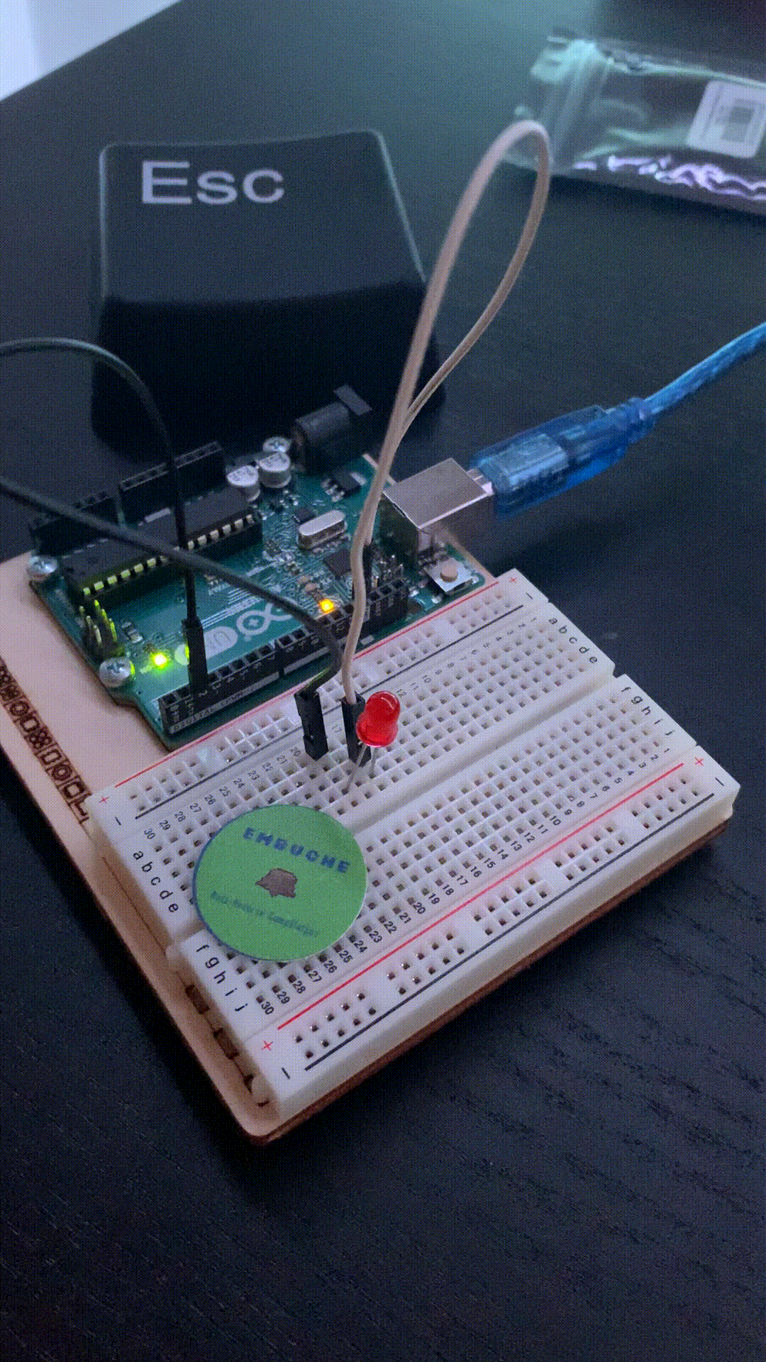
To be sure that the function wasn’t communicating with us through the pins I set up my logic analyzer (I bought for 10€ on Amazon).
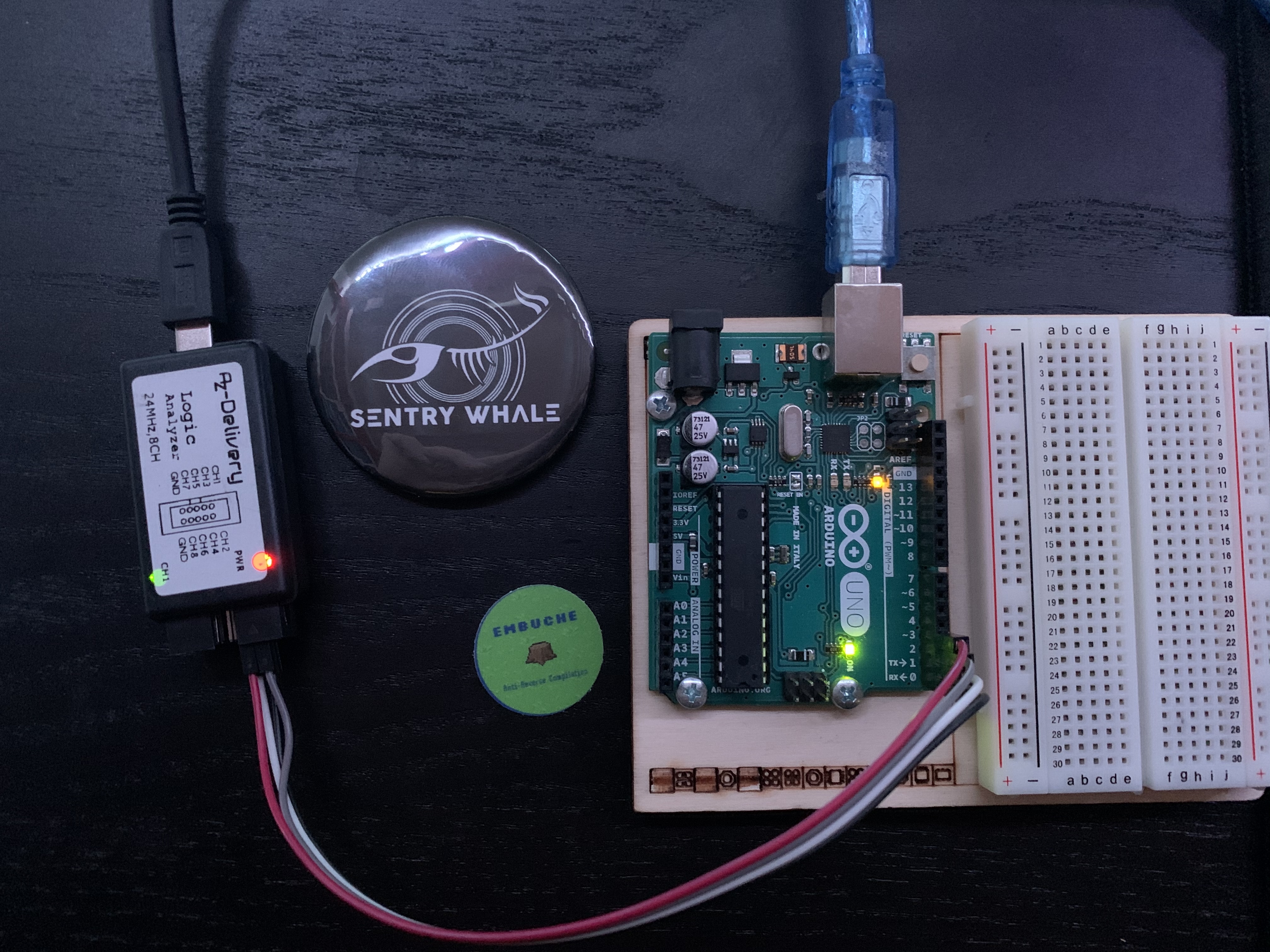
I only tested the first 4th to begin with.
I needed to install pulseview to use it
$ sudo pacman -S pulseview
$ sudo pacman -S sigrok-firmware-fx2lafw
The arduino was blank at the moment so I started the capture and uploaded the binary
sudo avrdude -F -V -c arduino -p ATMEGA328P -P /dev/ttyACM1 -b 115200 -U flash:w:/home/switch/nextcloud/CTF/dghack/reverse/strange/strange_thing.hexIn pulseview select fx2lafw driver for this devices
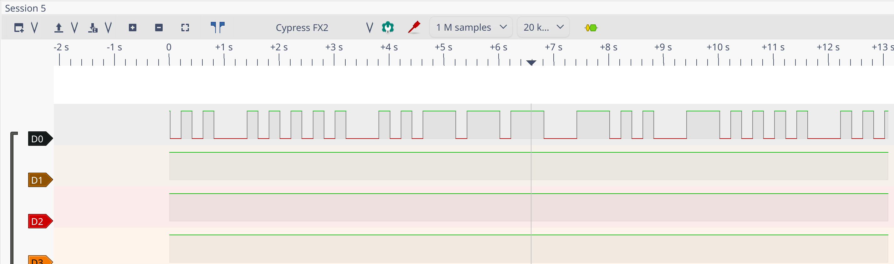
Hell yeah, communication through D0 which is the grey wire wired on pin 2 ! We can even set a led to see it has the frequency is very low.
Led encoding
I was wondering what it could be and then I think about the weird code I found earlier :
     3d2:       68 ec           ldi     r22, 0xC8       ; 200
     3d4:       70 e0           ldi     r23, 0x00       ; 0
     3d6:       80 e0           ldi     r24, 0x00       ; 0
     3d8:       90 e0           ldi     r25, 0x00       ; 0
     3da:       0e 94 dd 00     call    0x1ba   ;  0x1ba
     3de:       81 e0           ldi     r24, 0x01       ; 1
     3e0:       0e 94 70 00     call    0xe0    ;  0xe0
     3e4:       68 ec           ldi     r22, 0xC8       ; 200
     3e6:       70 e0           ldi     r23, 0x00       ; 0
     3e8:       80 e0           ldi     r24, 0x00       ; 0
     3ea:       90 e0           ldi     r25, 0x00       ; 0
     3ec:       0e 94 dd 00     call    0x1ba   ;  0x1ba
     3f0:       80 e0           ldi     r24, 0x00       ; 0
     3f2:       0e 94 70 00     call    0xe0    ;  0xe0
     3f6:       68 ec           ldi     r22, 0xC8       ; 200
     3f8:       70 e0           ldi     r23, 0x00       ; 0
     3fa:       80 e0           ldi     r24, 0x00       ; 0
     3fc:       90 e0           ldi     r25, 0x00       ; 0
     3fe:       0e 94 dd 00     call    0x1ba   ;  0x1ba
     402:       81 e0           ldi     r24, 0x01       ; 1
     404:       0e 94 70 00     call    0xe0    ;  0xe0
     408:       68 e5           ldi     r22, 0x58       ; 88
     40a:       72 e0           ldi     r23, 0x02       ; 2
     40c:       80 e0           ldi     r24, 0x00       ; 0
     40e:       90 e0           ldi     r25, 0x00       ; 0
     410:       0e 94 dd 00     call    0x1ba   ;  0x1ba
     414:       80 e0           ldi     r24, 0x00       ; 0
     416:       0e 94 70 00     call    0xe0    ;  0xe0
     41a:       68 ec           ldi     r22, 0xC8       ; 200
     41c:       70 e0           ldi     r23, 0x00       ; 0
     41e:       80 e0           ldi     r24, 0x00       ; 0
     420:       90 e0           ldi     r25, 0x00       ; 0
     422:       0e 94 dd 00     call    0x1ba   ;  0x1ba
     426:       60 e9           ldi     r22, 0x90       ; 144
     428:       71 e0           ldi     r23, 0x01       ; 1
     42a:       80 e0           ldi     r24, 0x00       ; 0
     42c:       90 e0           ldi     r25, 0x00       ; 0
     42e:       0e 94 dd 00     call    0x1ba   ;  0x1ba
     432:       81 e0           ldi     r24, 0x01       ; 1
     434:       0e 94 70 00     call    0xe0    ;  0xe0
     438:       68 e5           ldi     r22, 0x58       ; 88
     43a:       72 e0           ldi     r23, 0x02       ; 2
     43c:       80 e0           ldi     r24, 0x00       ; 0
     43e:       90 e0           ldi     r25, 0x00       ; 0
     440:       0e 94 dd 00     call    0x1ba   ;  0x1ba
I googled some operation and came across this gist : https://gist.github.com/zacharyvoase/5060886. This is an implementation of morse code in C for AVR. I already had the idea but wasn’t totally sure about it.
The code executed when matching a . is the following, with PERIOD = 100
    else if (currentChar == '.') {
      digitalWrite(led_pin, HIGH);
      delay(PERIOD);
      digitalWrite(led_pin, LOW);
      delay(PERIOD);
    }
The associated asm
1e0:    80 91 ce 01     lds r24, 0x01CE
 1e4:   61 e0           ldi r22, 0x01   ; 1
 1e6:   0e 94 f1 02     call    0x5e2   ; 0x5e2 <digitalWrite>
 1ea:   64 e6           ldi r22, 0x64   ; 100
 1ec:   70 e0           ldi r23, 0x00   ; 0
 1ee:   80 e0           ldi r24, 0x00   ; 0
 1f0:   90 e0           ldi r25, 0x00   ; 0
 1f2:   0b c0           rjmp    .+22        ; 0x20a <_Z10writeMorsePc+0x3a>
 1f4:   8d 32           cpi r24, 0x2D   ; 45
 1f6:   a9 f4           brne    .+42        ; 0x222 <_Z10writeMorsePc+0x52>
 1f8:   80 91 ce 01     lds r24, 0x01CE
 1fc:   61 e0           ldi r22, 0x01   ; 1
 1fe:   0e 94 f1 02     call    0x5e2   ; 0x5e2 <digitalWrite>
 202:   68 ec           ldi r22, 0xC8   ; 200
 204:   70 e0           ldi r23, 0x00   ; 0
 206:   80 e0           ldi r24, 0x00   ; 0
 208:   90 e0           ldi r25, 0x00   ; 0
 20a:   0e 94 4a 02     call    0x494   ; 0x494 <delay>
 20e:   80 91 ce 01     lds r24, 0x01CE
 212:   60 e0           ldi r22, 0x00   ; 0
This look very very similar to our code … Excepted that instead of 0x64 (100) we have 0xC8 (200). Let’s see in pulseview if it’s not time unit for one char.
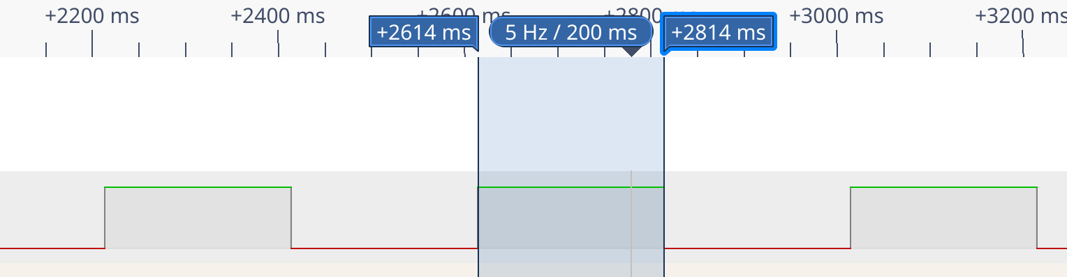
It is ! Hopefully there is a morse decoder in the tool (do not forget to set the time unit to 0,2)
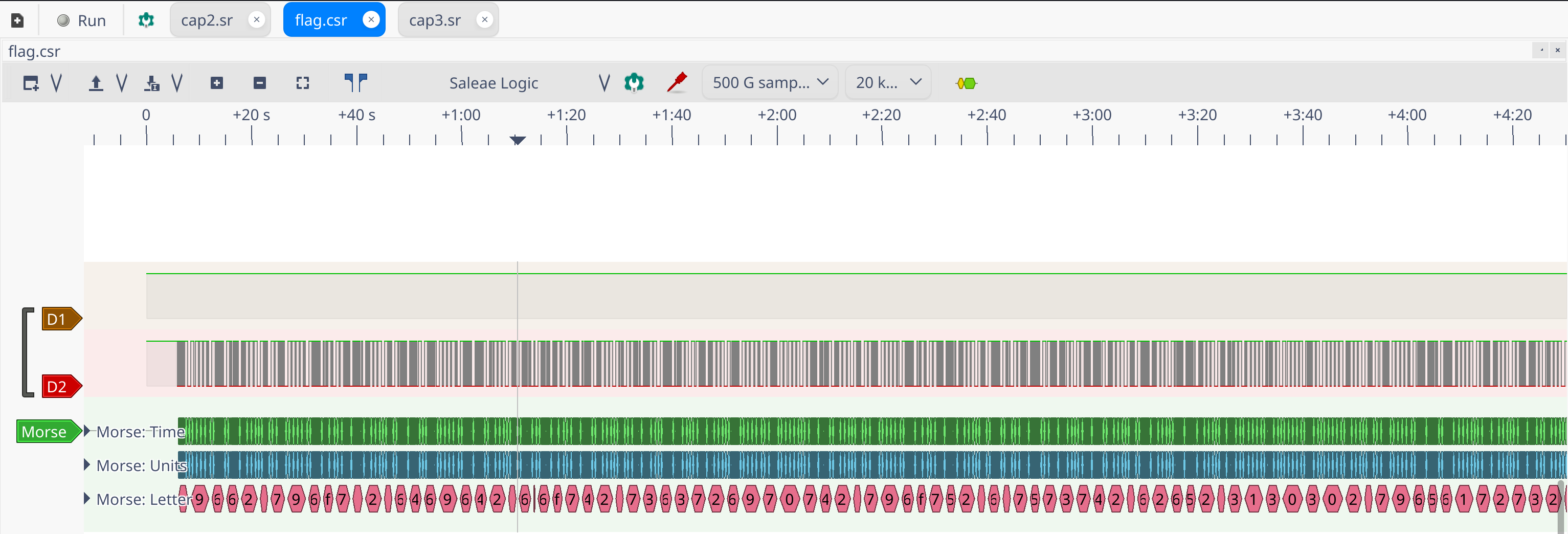
Once decoded we have a fucking long hex string and the led is still blinking.
v9662d796f752d6469642d6e6f742d7363726970742d796f752d6d7573742d62652d3130302d79656172732d6f6c642149662d796f752d6469642d6e6f742d73637269...However the first char is v which is not hex, the decoder interprets badly the first char. I figured out it was simply a 4 by looking at the morse code.
The hex once decoded will give : If-you-did-not-script-you-must-be-100-years-old!If-you-did-not-scri.. the flag !

sources
- https://blog.fox-it.com/2020/11/11/decrypting-openssh-sessions-for-fun-and-profit/
- https://www.youtube.com/watch?v=zk3JdMOQPc8&ab_channel=LiveOverflow
- https://research.kudelskisecurity.com/2018/09/25/analyzing-arm-cortex-based-mcu-firmwares-using-binary-ninja/
- https://blahcat.github.io/2017/10/13/flareon-4-writeups/
- https://github.com/buserror/simavr
- https://maker.pro/custom/tutorial/learn-the-basics-of-io-pins-for-an-avr-microcontroller
- https://www.fireeye.com/content/dam/fireeye-www/global/en/blog/threat-research/Flare-On%202017/Challenge9.pdf
- https://gist.github.com/zacharyvoase/5060886
- https://garretlab.web.fc2.com/en/arduino/inside/hardware/arduino/avr/cores/arduino/wiring_digital.c/digitalWrite.html
And the most important